Product Description
Product Description
DESCRIPTION:
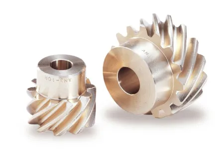
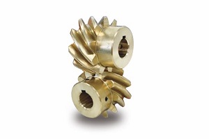
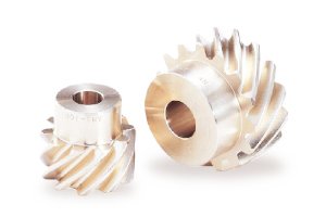
Gear reducers are enclosed helical gears with hollow inputs.
The gear is mounted directly on the input shaft of the gear and receives support from a motor mounting bracket mounted on the machine housing.
No additional parts are required to transfer torque from the reducer to the machine.
It can be mounted in vertical, horizontal or inclined position.
Shaft-mounted gear reducers typically have 5:1 7:1 10:1 reduction ratios and output speeds ranging from 1 to 300 rpm.
M4 series gear reducer can be installed directly on screw conveyors and feeders with a XUH seal installed on the output shaft of the gearbox.
Ensure that cement, and fly ash powder will not get into the gearbox and extend the service life of the gearbox.
More suitable for bulk materials, grain and aggregate handling industries
WORKING PRINCIPLE:
M4 series gearboxes come in 5 sizes (M41 / M43 / M45 / M47 / M49).
Nominal gear ratios are in accordance with Ra 10 CHINAMFG 2017 (5, 6, 7, 10). Cylindrical gears with helicoidal teeth.
M4 series gearboxes can be mounted directly on screws: in this case, the XUH type output shaft seal is usually installed.
M4 series gearboxes are supplied with grease for use at ambient temperatures (0°C – 40°C).
PROPERTIES:
– Helical gearbox
– Nominal torque that can be transferred to the output shaft: up to 1500 Nm.
– Installed power at the input up to 30 kW.
– Operation at ambient temperature (0°C – 40°C).
– DIN 5482 involute spline output shafts
– Flange mounting on motor and output side
– Precision-machined cylindrical bevel gears with teeth.
– Flange mounting on motor and output side
BENEFITS:
– Easy installation
– Quick maintenance
– Low installation costs
Services
Pre-sales Commitment
1. For user inquiries, quick response, warm reception, and answer all questions.
2. Provide detailed design information free of charge within 24 hours.
Commitment in Sales
1. All ex-factory products meet the quality standards specified in the contract. All products are tested according to customer requirements before delivery.
2. After the contract is signed, the customers are welcome to the site of our company for supervision.
After-sales Commitment
1. We provide technical support for customers. If necessary, the product can be debugged on-site, and relevant operators can be trained to solve user problems.
2. 24 hours to solve the problems for customers. Product use a day, a day of service.
3. Set up a high-quality service team, and set up product files for regular return visits.
| Application: | Machinery |
|---|---|
| Hardness: | Hardened Tooth Surface |
| Installation: | Vertical Type |
| Layout: | Coaxial |
| Gear Shape: | Conical – Cylindrical Gear |
| Step: | Four-Step |
| Samples: |
US$ 100/Piece
1 Piece(Min.Order) | |
|---|
| Customization: |
Available
| Customized Request |
|---|
How do you install a screw gear system?
Installing a screw gear system, also known as a worm gear system, requires careful consideration and precise execution. Here’s a detailed explanation of the steps involved in installing a screw gear system:
- Design and Selection: Before installation, it is crucial to design and select the appropriate screw gear system for the specific application. Consider factors such as required torque, speed, load capacity, gear ratio, and environmental conditions. Choose a screw gear system that matches the application’s requirements and ensure compatibility with other components and machinery.
- Prepare the Components: Gather all the necessary components for the screw gear system installation, including the worm gear, worm wheel, bearings, shafts, and any additional accessories or support structures. Inspect the components for any damage or defects and ensure they are clean and properly lubricated.
- Mounting the Worm Gear: Begin the installation by mounting the worm gear. Securely attach the worm gear to the appropriate shaft or motor using suitable fasteners. Ensure that the alignment of the worm gear is accurate, and it is properly centered on the shaft to avoid any misalignment issues during operation.
- Mounting the Worm Wheel: Once the worm gear is in place, mount the worm wheel. The worm wheel should be positioned in such a way that it meshes smoothly with the worm gear. Ensure that the worm wheel is securely mounted, and any necessary bearings or supports are properly installed to maintain stability and alignment.
- Alignment and Adjustment: Proper alignment of the screw gear system is crucial for its efficient operation. Ensure that the worm gear and worm wheel are correctly aligned both axially and radially. Check for any excessive play or binding in the system. Make necessary adjustments to achieve optimal alignment and smooth meshing between the gears.
- Lubrication: Apply the recommended lubricant to the screw gear system. Proper lubrication is essential to minimize friction and wear, ensuring smooth operation and extending the system’s lifespan. Follow the manufacturer’s guidelines regarding the type and amount of lubricant to use.
- Testing and Fine-Tuning: After installation, perform thorough testing of the screw gear system. Check for smooth operation, proper engagement between the gears, and any abnormal noise or vibration. Fine-tune the system if necessary, making adjustments to achieve the desired performance and ensure optimal functionality.
- Regular Inspection and Maintenance: Once the screw gear system is installed and operational, it is important to establish a regular inspection and maintenance schedule. Regularly inspect the system for signs of wear, lubrication levels, and any potential issues. Perform routine maintenance tasks such as cleaning, lubrication replenishment, and component replacement as needed.
It is crucial to follow the manufacturer’s guidelines and specifications during the installation process. If unsure about any aspect of the installation, consult with experts or refer to the manufacturer’s documentation for detailed instructions specific to the screw gear system being installed.
How do you ensure proper alignment when connecting screw gears?
Ensuring proper alignment when connecting screw gears is crucial for their efficient and reliable operation. Proper alignment helps minimize noise, vibrations, and premature wear, resulting in improved performance and longevity of the gear system. Here’s a detailed explanation of how to ensure proper alignment when connecting screw gears:
- Use Precision Machining: Achieving accurate alignment starts with precision machining of the gear components. The worm gear and worm wheel should be machined to tight tolerances, ensuring proper tooth profile, pitch, and concentricity. High-quality manufacturing processes help ensure the components are dimensionally accurate, which facilitates proper alignment.
- Consider Mounting Configuration: The mounting configuration plays a significant role in aligning screw gears. Whether the gear system is mounted on a shaft or a frame, it is important to carefully follow the manufacturer’s guidelines or engineering specifications for proper mounting. This may involve using specific mounting hardware, such as flanges, couplings, or adapters, to ensure secure and precise alignment.
- Verify Axial Alignment: Axial alignment refers to the alignment of the worm gear and the worm wheel along the gear’s axis of rotation. To verify axial alignment, measurements such as center distance, parallelism, and axial runout should be taken. Precision measuring tools, such as dial indicators or laser alignment systems, can be used to ensure the components are aligned within the specified tolerances.
- Check Radial Alignment: Radial alignment refers to the alignment of the worm gear and the worm wheel in the radial direction. It ensures that the gear meshing occurs at the proper contact point along the gear teeth. Radial alignment can be checked by measuring the radial runout or tooth contact pattern. Adjustments can be made by shimming or using spacers to achieve the desired alignment.
- Consider Preloading: Preloading the screw gear system can help improve alignment and reduce backlash. Preloading involves applying a controlled axial force to the gear components to eliminate any clearance or play between the teeth. This can be achieved through various methods, such as using adjustable bearings or applying a preloaded spring mechanism. Preloading should be done within the manufacturer’s recommendations to avoid excessive loading that could lead to premature wear or damage.
- Follow Manufacturer Guidelines: Manufacturers often provide specific guidelines and recommendations for aligning their screw gear products. These guidelines may include recommended tolerances, alignment procedures, and suggested tools or techniques. It is important to carefully review and follow these guidelines to ensure proper alignment and to maintain any warranty or support provided by the manufacturer.
- Consult with Experts: If you are unsure about the alignment process or encounter challenges in aligning screw gears, it is beneficial to consult with experts or experienced engineers. They can provide guidance, troubleshooting assistance, or even perform precision alignment using specialized equipment or techniques.
By following these practices and taking the necessary alignment measures, you can ensure proper alignment when connecting screw gears. This alignment process helps optimize the performance, efficiency, and service life of the gear system.
Are there different types of screw gears available?
Yes, there are different types of screw gears available, each with its variations in design and functionality. These variations cater to specific applications and requirements. Here are some of the commonly used types of screw gears:
- Single-Thread Worm Gears: Single-thread worm gears have a single helical thread on the worm. They provide a relatively higher gear ratio and are commonly used in applications requiring moderate torque and precision positioning. Single-thread worm gears are widely employed in industries such as manufacturing, automotive, and machinery.
- Multi-Thread Worm Gears: Multi-thread worm gears have multiple helical threads on the worm, typically two or more. The presence of multiple threads increases the contact area and allows for higher torque transmission. Multi-thread worm gears offer higher gear reduction ratios and are suitable for applications requiring greater torque multiplication, such as heavy-duty machinery and high-load lifting systems.
- Fine-Pitch Worm Gears: Fine-pitch worm gears have a smaller pitch, meaning there are more teeth per unit length of the worm. This design allows for finer control and precise positioning. Fine-pitch worm gears find applications in industries where accurate motion control is critical, such as robotics, automation, and optics.
- Coarse-Pitch Worm Gears: Coarse-pitch worm gears have a larger pitch, resulting in fewer teeth per unit length of the worm. This design provides higher torque transmission and is suitable for applications requiring heavy-duty power transmission. Coarse-pitch worm gears are commonly used in industries like manufacturing, material handling, and conveyors.
- Right-Handed and Left-Handed Worm Gears: Screw gears can be classified as right-handed or left-handed based on the direction of the helical thread. In a right-handed worm gear, the helical thread advances in a clockwise direction when viewed from the end of the worm. In a left-handed worm gear, the helical thread advances counterclockwise. The choice between right-handed and left-handed worm gears depends on the specific application and the desired rotational direction.
- Non-Throated and Throated Worm Gears: Non-throated worm gears have a cylindrical worm without a groove, while throated worm gears have a groove or a notch on the worm. The presence of a throat allows for greater contact between the worm and the worm wheel, increasing the gear meshing efficiency and load-carrying capacity. Throated worm gears are commonly used in applications where higher efficiency and load capacity are required.
- Self-Locking Worm Gears: Self-locking worm gears are designed to have a high self-locking capability. The helical thread angle and the friction between the worm and the worm wheel prevent the worm wheel from backdriving the worm when the system is at rest. Self-locking worm gears are widely used in applications that require holding a position without the need for additional braking or locking mechanisms, such as elevators, lifts, and positioning systems.
These are some of the different types of screw gears available in the market. The selection of a specific type depends on factors such as torque requirements, gear reduction ratio, precision positioning, load capacity, and self-locking capabilities, among others. Understanding the characteristics and variations of screw gears allows for choosing the most suitable type for a given application.


editor by CX 2023-11-10